Minimizing Risk in Offshore Submerged Arc Welding
Minimizing Risk in Offshore Submerged Arc Welding
Increasing deposition rates in submerged arc welding requires proper selection of consumables for achieving consistent toughness and low diffusible hydrogen weld deposits
by Ben Schaeffer and Teresa Melfi, The Lincoln Electric Company
Weld integrity, quality and consistency are compatible with higher welding productivity and lower fabrication costs, as long as key factors are taken into consideration. The effect of diffusible hydrogen, the selection of alloy systems and the choice of welding procedures all play a crucial role in maintaining high quality and consistency in offshore weldments.
Welders and Welding Engineers face distinct challenges in an era of increased scrutiny by governmental regulations, owner’s representatives and agency classification societies. Owner representatives are closely monitoring the welding activity of yards, commonly looking for less than one percent defect rate in overall welding performance before contracts are awarded. This requires that the design engineering, fabrication and construction firms re-think the margin of safety in their welding processes. To reach first oil or gas in deep water, designs incorporating higher strength materials are increasingly common, as are higher productivity welding procedures, even in automated processes such as submerged arc welding (SAW). However, changes in welding variables can also increase hydrogen content, further influencing the risk of delayed cracking. Hydrogen-related cracking is known to be a function of the quantity of hydrogen, the susceptibility of the microstructure and the residual stresses on the metal. Welding procedures and practices influencing the diffusion of hydrogen are often overlooked. Increased productivity in welding almost always results in thicker individual weld passes and more weld passes per hour (for less time between passes). The result is larger diffusion distances, shorter periods of time for hydrogen to escape and an increased risk of hydrogen related cracking. These factors, especially when combined with the microstructures of higher-strength steels common to the offshore welding industry, require a new look at hydrogen control in every aspect of welding.
In addition to an increased risk of hydrogen cracking mechanical properties such as Crack Tip Opening Displacement (CTOD) toughness often suffer when larger weld beads are deposited with conventional welding consumables and processes. This article quantifies the risk factors beyond those explored in standardized diffusible hydrogen and CTOD testing, dispelling some commonly held beliefs and proposing others. From this, options are established to mitigate these risks in the real-world environment of heavy offshore structures. As such, it’s important that offshore firms increase their technical requirements for welds and look to new technologies and strategies to maintain consistency and quality of weld deposit properties as well as achieve higher productivity. For SAW, this is achieved through welding procedure upgrades in combination with proper selection of welding consumables.
Increasing Productivity with AC Technology
Fabrication of offshore platforms and components requires an unwavering commitment to the quality of welding but also a commitment to carefully managed costs and production schedules. A new technology in SAW power sources is AC Waveform Control. As shown in Figure 1, AC Waveform Control permits significant increases in electrode deposition rates, allowing for higher weld productivity at the same average heat input.
<table summary="" style="color: rgb(51, 51, 51); font-family: Arial, Helvetica, sans-serif; font-size: 11px; font-style: normal; font-variant-ligatures: normal; font-variant-caps: normal; font-weight: 400; text-align: start; background-color: rgb(255, 255, 255); width: 781.6px;"><tbody><tr><td colspan="3" style="vertical-align: top;"><p align="center"><strong>Figure 1: Increased Deposition Rates Achieved with the Power Wave® AC/DC 1000 SD</strong></p></td></tr></tbody></table><br><p style="color: rgb(51, 51, 51); font-family: Arial, Helvetica, sans-serif; font-size: 11px; font-style: normal; font-variant-ligatures: normal; font-variant-caps: normal; font-weight: 400; text-align: start; background-color: rgb(255, 255, 255);"></p>


$name
The outcomes are reduced welding and operational costs and increased weld team productivity in single- or multi-arc welding applications. And, with input current requirements reduced by up to 50 percent for some of the newest inverter-based SAW systems, users consistently report significant energy savings over traditional SAW equipment. Increased deposition rates do not come without a price, however. That price is risk; specifically, risk of failing mechanical properties (toughness) and risk of hydrogen related cracking.
CTOD Toughness and Consumable Selection
The productivity increases delivered through SAW AC waveform control are associated with higher deposition rates, often accompanied by thicker individual weld passes. Many alloy systems develop toughness when as-deposited weld metal is reheated and refined by subsequent weld passes (see Figure 2). Thicker weld beads resulting from higher deposition rates can affect mechanical properties by increasing the percentage of as-deposited (unrefined) weld metal. Unrefined weld metal is associated with coarser grain microstructure, more grain boundary ferrite and lower toughness in Mn-Si (mild steel) and Mn-Si-Ni alloy systems.

Figure 2: Weld-Metal Refinement in a Submerged Arc Weld
Weld bead size and placement are especially influential on weld deposit toughness when such alloy additions are not engaged. Smaller weld beads and more passes ensure higher content of refined weld metal but limit welding productivity. Technology advances in Submerged Arc Welding fluxes allow for better toughness in the unrefined weld metal of mild steel and low alloy systems without making traditional sacrifices to diffusible hydrogen or ease of welding at higher deposition rates. Table 1 shows that CTOD toughness @ -10 °C of predominantly unrefined weld metal (WCL + 5mm, see Figure 2) approaches that of predominantly refined weld metal (Weld Centerline (WCL), see Figure 2) for both mild steel and low alloy deposits when using a welding flux designed accordingly. These results show consistent toughness throughout a weld deposit even at a higher overall concentration of unrefined weld metal and imply a reduced risk of toughness related failures is possible when modifying joint designs and welding procedures for improvements to productivity.

Table 1: Through-Thickness CTOD Values @ -10 °C for a Mild Steel Weld Deposit; Weld Centerline (WCL) consists of mostly refined weld metal and WCL + 5mm consists of mostly unrefined weld metal, see Figure 2 for a depiction of CTOD test location
Consistent CTOD values for a weld deposit may also serve as its own productivity improvement. CTOD values quantify a weld’s resistance to ductile crack propagation. During the multiple-pass welding of thick sections, residual stresses accumulate which deteriorate a weld’s ability to resist ductile crack propagation (and reduce CTOD values). Post Weld Heat Treatment (PWHT) is often used by fabricators to relieve residual weld stresses. According to Offshore Standard DNV-OS-F101:
Post weld heat treatment shall be performed for welded joints of C-Mn and low alloy steel having a nominal wall thickness above 50 mm, unless fracture toughness testing shows acceptable values in the as welded condition.
Consistent CTOD values in the as-welded condition eliminate the need for PWHT, significantly reducing cost and improving productivity.
Diffusible Hydrogen and Consumable Selection
Proper selection of welding consumables is also vital at higher deposition rates to resist a common failure – delayed hydrogen cracking in the thicker weld beads.
Qualification of materials and welding procedures used in critical structural offshore and pipeline applications often includes extensive welding and testing under production conditions for validation of mechanical properties, including CTOD toughness. Because diffusible hydrogen testing is extremely difficult to quantify outside of a laboratory, the same is not true for its validation. Further complicating the situation is the fact that most offshore yards are in high humidity areas near the sea. These factors makes it even more critical that a SAW wire and flux combination are robust in their ability to deposit low hydrogen weld metal – both directly out of the bag and after exposure to humid environments.
Failure mode rankings use frequency, severity and detectability of defects in determining a rating of risk. Diligent fabricators may consider the frequency of hydrogen cracking to be low. Cracking in the welds of any subsea pipeline or component is a severe defect, with increased risk of in-service failure due to the difficulty associated with detecting hydrogen cracks. Hydrogen cracks may initiate immediately or days after welding. Figure 3 shows that although the measured volume of hydrogen increases with subsequent weld passes, weld metal hydrogen has been measured to be most concentrated (i.e., hydrogen per 100 grams weld deposit) in the first weld passes of a multiple pass joint. In this case, hydrogen cracks may be located deep within a weld joint (common offshore joints are as deep as 3 or 4 inches) requiring sophisticated NDT techniques for detection and great expense to repair.

Figure 3: Diffusible Hydrogen in a Multiple Pass Weld
The cross-section of a hydrogen crack (Figure 4a) from a high strength weld indicates that such cracks may also initiate immediately. This crack was shown to originate in the first pass of a multiple pass weld. The exposed crack surface (Figure 4b) confirmed immediate cracking as heat tint was found in the first pass region. The factors of severity and detectability yield a high risk associated with hydrogen cracks in structural offshore welds.
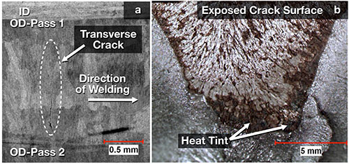
Figure 4: Example of Hydrogen Cracking in a Multiple Pass Weld
As shown in Figure 5, increasing time between weld passes (especially at interpass temperature) is effective for reducing diffusible hydrogen content. Although increasing preheat and interpass temperatures helps to mitigate the risk of hydrogen cracking, such practices may also reduce weld metal strength. Other methods of lowering diffusible hydrogen (interpass hold times and dehydrogenation soaks) reduce productivity. Again, avoiding such practices makes the selection and handling of consumables especially important.

Figure 5: Diffusible Hydrogen Time-Decay for a Single Pass Weld; more than one hour was necessary for a specimen (held at 250 °F) to halve its initial diffusible hydrogen content
All SAW fluxes (both agglomerated and fused) have a unique correlation between moisture content and diffusible hydrogen. Flux moisture characteristics are equally important in minimizing risk for hydrogen related cracking. This relationship limits the minimum achievable hydrogen content for a given flux, even after pre-baking or pre-drying the flux. Figure 6 pictures the difference between diffusible hydrogen obtained from a welding flux that is considered to be an industry standard for use in offshore welding applications in Europe and Asia compared to that of a flux designed and manufactured with new technologies. A new flux developed for use in offshore welding applications – Lincolnweld® 842-H™ – is unique in the market. It has been designed to produce ultra-low diffusible hydrogen, typically less than 3 mL/100g of deposited weld metal on both AC and DC polarity, reducing the likelihood of weld metal hydrogen cracking. This is valuable for the offshore construction industry where consistency in operability, impact toughness and low diffusible hydrogen are critical.

Figure 6: Hydrogen diffusing from two weld samples; samples were welded and tested using the same procedures; diffusible hydrogen values correspond to the “As-Received” condition in Figure 7
The ability to use a flux with no pre-conditioning reduces cost and complexity, while minimizing the chance for error during handling. New technology used in the design, manufacture and packaging of welding flux allows for the welding of Lincolnweld® 842-H™ directly from its package. Here, the new technology is again compared with that of the “industry standard” flux, and the magnitude of the difference in diffusible hydrogen after exposure is astounding. Fabricators and inspectors are often comfortable with a diffusible hydrogen level of 5 ml per 100g of weld metal but would be rightfully concerned with a value of near 15 ml per 100g of weld metal!

Figure 7: Diffusible Hydrogen of Fluxes Upon Humidifcation; the hydrogen potential for As-Received flux as well as for flux exposed to high humidity should be minimal to reduce the risk of hydrogen related cracking
Conclusion
Specifying consumables for deepwater and ultra-deepwater SAW applications requires forethought and diligence in order to produce robust welds that not only stand up to harsh environments but also meet increasingly stringent industry quality and testing standards, such as CTOD values.
Welding with AC waveform control on the latest inverter AC/DC power sources has the potential to greatly increase productivity. This, combined with a high toughness, low hydrogen flux can achieve the goals of lowering costs while lowering risks. New technologies applied to SAW power source and flux design make this all possible.
Originally printed in the American Welding Society Welding Journal, March 2013.